Astronomy: equipment 9
Speckle sub-micron position sensing
Updated: Jul 2026
Click here to better view this site
INTRO - TELESCOPE DRIVES - STAR CENTROID GUIDING:
Telescopes are driven by a mechanism to counter the spin of the earth so as to keep the sky fixed at the eyepiece or camera. These mechanisms exhibit all manner of imperfections, degrading long exposures. The common method to compensate for them is with an imaging setup taking short images and locating the stars' centers to compute a compensation for the motor drive(s). These images are either taken through the main telescope or from a smaller telescope mounted off axis to it. The guide exposures can vary from sub-second to some 5 seconds. The longer the delay, the more likely the compensation will be late and cause star images to drift, smearing them on the camera sensor.
MECHANICAL INACCURACIES:
In order to compensate for these inaccuraries, one needs to detect at least 1 arc-sec of deviation from the refracted sidereal rate of approx 15 arcsec/sec, a tiny angular dimension! The problem can be mitigated with state of the art drives and mounts, which are exceedingly costly, or having very high resolution (23+ bits) linear encoders to detect the deviation from the ideal, and these too are very expensive. Always seeking for low cost solutions, I wanted to detect the right ascension axis motion by taking highly magnified images of a large disk on that axis to image its surface roughness. Initial trials of a high DPI optical mouse having a lens that focuses the target surface onto a tiny sensor of very high sensitivity met with failure because my tests proved the pixels are 40 um - the 26K DPI is more hype than fact, and would not deliver anywhere near the sensitivity I required. This information is highly guarded and cannot be found on the internet - I had to carry out the experiment to find it - great effort via SPI and C code on a Teensy 4.0 with the OEM sensor.
OPTICAL SENSING:
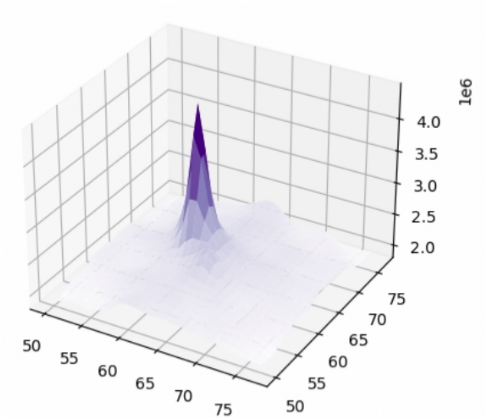
The next concept was a microscope lens on a monochrome sensor to image the target surface. Convolution of two subsequent images would yield the cartesian shift between these from their convolution correlation peak. However this is far too much computation for todays affordable SBCs, the alternative is to convert the two images to the frequency domain via 2D FFT (fast Fourier transform), then cross product these FFTs, resulting in a correlation peak the phase of which determines the shifts. More on that later...
... SPECKLE!
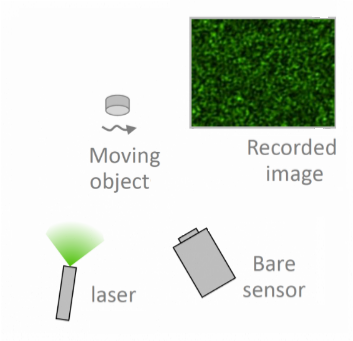
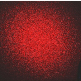
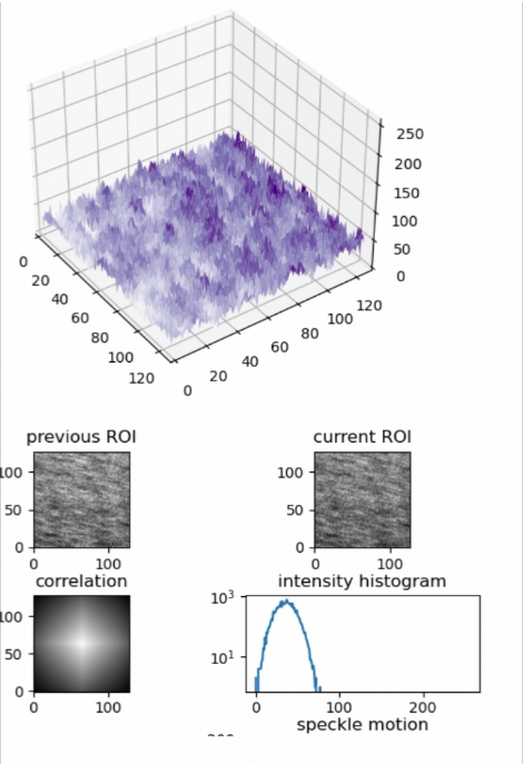
But before trying a microscope design, I mused that the speckle pattern from coherent light shinning on a target surface, affordably had by a laser diode, would do just as well and not require a lens nor focusing - a very simple sensor! The speckle field created by the roughness of the imaged surface (here the telescope mount disk(s)) reaches the bare CMOS detector - the pattern moves with the disk. The near field mean speckle size scattered off a rough diffuser is √( λ · z ) [Dainty 1975], where λ = coherent light wavelength, z = distance target to sensor. Anodized aluminum and oblique lazing lowers the mean size - I adjusted to render mean speckles of 10 pixels across
THE SENSOR:
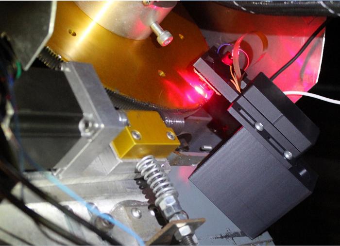
I secured a 5mW 628nm red laser diode, had on hand an RPI colour camera with an IMX219 sensor (1.1x1.1um pixel, RGGB bayer matrix) and tested the concept. It looked promising after coding and testing on an RPi4, so I 3D printed a bracket and installed to laze and image the 10" right ascension gear of the RC16. Using a colour sensor is not ideal, but it was telling enough to upgrade to the monochrome OV9281 sensor (3x3um pixel).
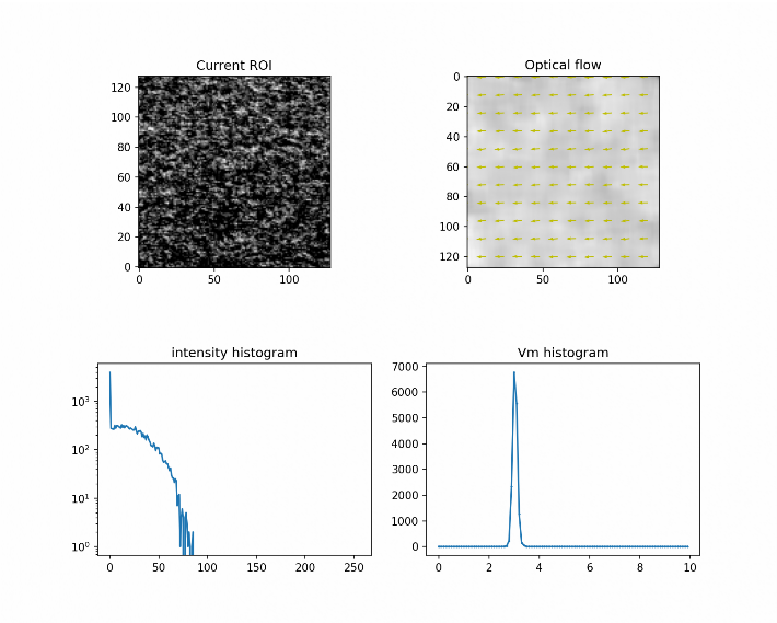
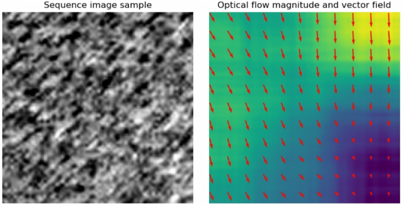
Many weekends later, the python script cycles the laser on/off to capture a background image (similar to a dark frame in astroimaging terminology), computes a flat frame from 1000 lazed images, test for the proper exposure time (10 us! very bright), and finally snaps very short and very small (64x64 pixels) region of interest (ROI) to expedite the computations. These images are taken every 1/4 second, and indeed each is a stack of 4 frames to mitigate shot noise which otherwise deteriorates the correlation - it is carried out between two images seperated by 1 second to ensure a better result, so 4 shift results occur per second. I had initially used FFT correlations which were very fast (10 frames/sec), but that proved too noisy, so moved to using Lucas-Kanade 'optical flow' which does DFTs (discrete Fourier transform) on a region around each pixel in the image. The resulting set of cartesian optical vectors provide a direction and magnitude for the disk's movement in the sensor's field. If the X or Y axis is properly oriented, the motion will be mostly in one axis.
RESULTS:
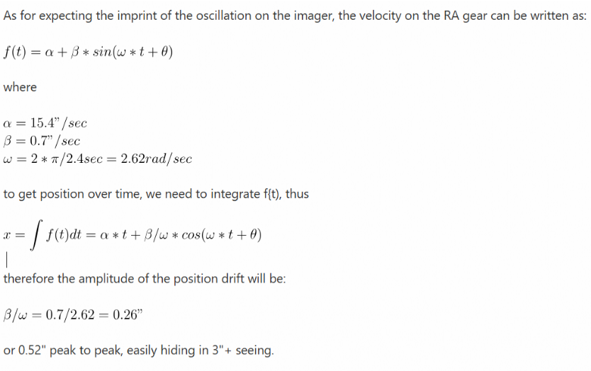
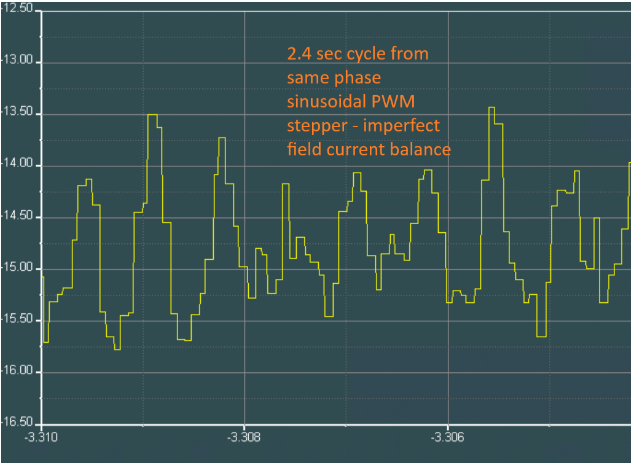
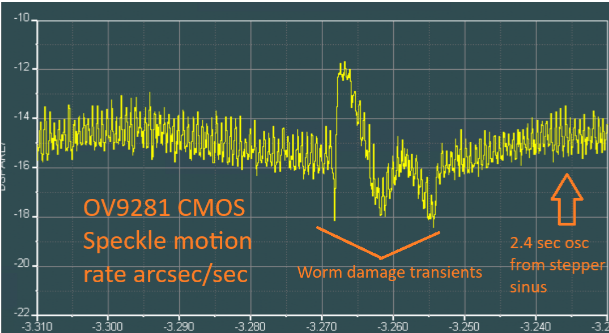
Optical flow was as good as I could make it, yet there was a 1.5 arcsec oscillation at 2.4 second period in the 15 arcsec/sec sidereal rate which I had attributed to some as yet not understood sensor artifact. But the 2.4 sec period existed with the much smaller pixel of the colour camera as well as the monochrome. The worm in my drive has a 240 second period... wait, that's 100 times the oscillation, and the motor is a 200 step motor (Servo57D), 2.4 sec was exactly the period between one of the stepper coil spacing! that oscillation is the inaccuracy in the sinusoidally PWM driven coils and flux path inaccuracies! A further proof is that plotting the sensed rate to motor/worm shaft had all of the oscillations line up across 10 worm cycles. I wondered why I didn't see this in the star images making them quite unround - and here's why (was actually worst as 2.4 sec was exciting the scope's mechanical resonance):
HOW GOOD IS IT?
The sensor at 4.5" radius of the RC16 right ascension gear results in 0.55 um per arc-sec. Thus at sidereal rate of 15 "/s, the speckle pattern on the OV9281 CMOS sensor will move 8.33 um, or 2.77 pixels per second. The sensor is achieving better than 0.3 um resolution, thus it is sensing around an arc-sec of sky, very fine indeed.
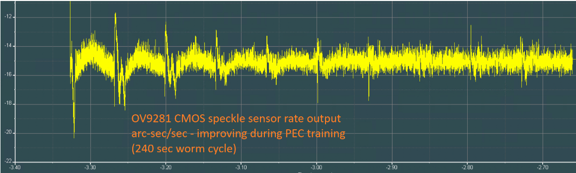
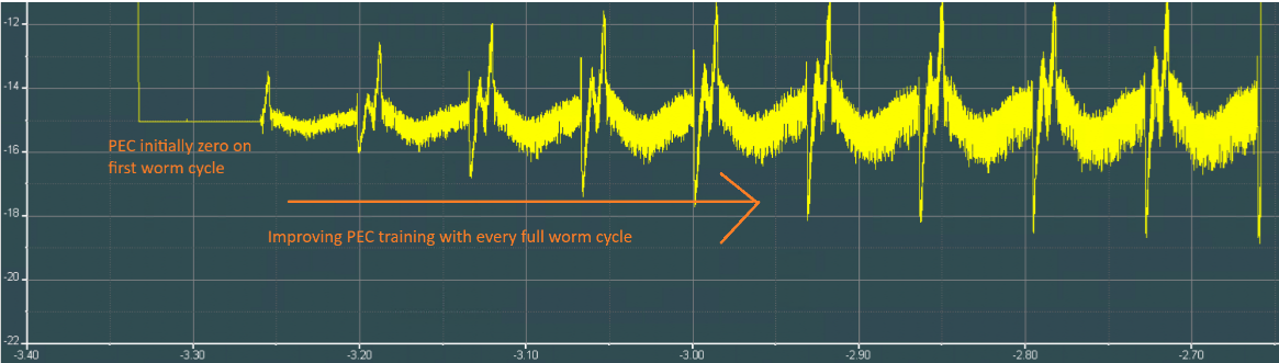
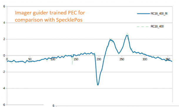
Most telescope mounts use a periodic error correction (PEC) to compensate for gross mechanical errors, and is had by centroiding stars from guide images to train the PEC over many cycles of the worm or gear train. To the right (white graph) is the one from my RC16 - it has 400 look up table entries to compensate the rate sent to the motors (vertical axis is "/sec, horizontal is worm angle). The nasty transitions are not expected in a PEC, and is from an impact of my telescope with the dome interior - having no friction clutch, the heavily geared motor at the time marred the steel worm. The transient is so fast that the PEC is insufficient to prevent stars trailing in that region. Changing the gear is a costly affair, 2000$. Enter SpecklePos! the two graphs below show the re-training of the PEC using SpecklePos where the top graph is the sensor output and the lower is the live PEC correction. You see the mechanical errors fade away from the sensor pickup and transfer into the PEC. The 2.4 oscillation I spoke of earlier is not being purged because I'm still trying to figure the proper phase (horizontal axis = local time in hours before midnight, vertical = rate "/sec). Anecdote: I realized that when I had trained the PEC by camera guiding on a bright star much before SpecklePos was even a concept, a 3.6 deg variation would appear - the very same stepper motor artifact!
The 2.4 sec oscillation shown at right. It's blocky because the speckle images are taken every 0.25 sec. However the computed rate is between images separated by 1 sec, so even though the rate shows up 4 times per second, its already 0.5 second old (half of 1 sec). It would be difficult to use this in a control loop, never mind the 2.4 sec oscillation, but for PEC training, it does fine. Note the PEC table was increased to 960 entries to handle all 960 speckle results over a worm cycle - to ensure the PEC can compensate for quick transients that my scope is afflicted with.
I wanted to reduce the time to compute the optical flow field, either by using the GPU (a lot of work, high probability of failure), or using OpenCV in lieu of Scikit-image as unlike the latter, OpenCV is highly optimized C++ compiled libraries. Lo and behold, see how much faster it is! (both are dense field optical flow, that is at each pixel, on a 64x64, 8 bit monochrome image):
130 ms Scikit-image optical_flow_ilk()
3 ms OpenCV calcOpticalFlowFarneback()
Over 40x faster. The quality of the vectors is just as good with OpenCV, allowing more updates per second if the camera sensor will permit it (resolution, sensitivity, laser brightness, ...). No point in trying out a GPU! It also allows SpecklePos to run on a Pi zero2W, whereas it was impossible with Scikit-image.
WHERE NEXT?
I am still trying to compensate for the 2.4 sec oscillation, but the stepper motor doesn't seem to be responding despite the rate at which my controller is pulsing it and responding to the PEC.
I could reduce the oscillation by using servo motors or doing the sinusoidal drive myself as I've already proven I can do better than the Servo57D stepper and indeed than the top of the line Gecko drives. They don't because they don't cater to the incredibly slow speed at which we drive telescopes, never mind the slew rates we need to move to the next target and the considerable inertia present. But for now, I'll stick with this stepper since the impact on the star shape is minimal.
With a Pi zero 2W, there is only enough resources to muster 3 maybe 4 samples per second, so it is not recommended to use one over a RPi 4b.
EXPANDING FURTHER - ABSOLUTE POSITION:
there is a shortcoming in using optical flow on a small ROI (computational expense), that it fails to pick up fast motion on such a small ROI on the order of 2 arcmin/sec. The FFT correlator is far better, achieving 2 deg/sec detection because a larger ROI can be had due to the very fast algorithm. Another problem is that small errors will build up over time making it a poor substitute of a guide camera.
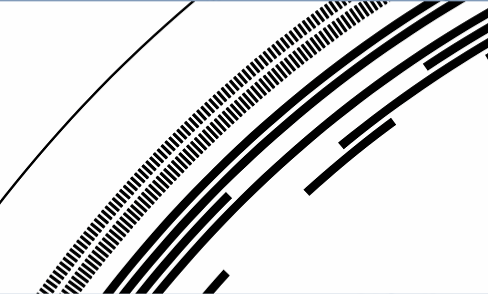
One possible solution is to print two fine sets of bands on the disk, as well as tiny bar codes say every 3 degrees whence another low cost camera would image these (or a second ROI from the SpecklePos camera) - the alternating dual bands would serve as two phase encoding, whereas the barcode would provide absolute position. It's simple to do this under Python. Coupled with the SpecklePos sensor, the absolute position could be very well estimated down to a fraction of a micron, and whether the telescope is on an equatorial or azimuthal mount, the two axes suitably encoded would yield the coordinates and required motor rate(s) sans guide camera.
A second solution is printing absolute positions as gray code on the disk (fewer errors as one bit changes at a time). The printing medium is probably the limiting factor and I'd surmise no better than 1/3 mm, thus at 5" radius is some 2400 positions or 11 bits, corresponding to 10 arc-mins. In my opinion that is 5 to 10 times larger than would be needed to mate with SpecklePos, so it's likely the SpecklePos Python code would need to do an FFT correlation for faster rates.
For now, I'll stick to camera guiding, augmenting tracking with SpecklePos to increase the guiding bandwidth and accuracy.